
Steel-to-concrete connections conclusively regulated by Eurocode
All construction projects have at least one steel-to-concrete connection, whether it is a steel beam and a concrete wall, a canopy outside of a building or even balustrades.
Solutions can be cast-in or post-installed fasteners, which are often called concrete anchors. In March 2019, the European Committee for Standardization (CEN) officially published a new part of Eurocode 2 regulating safety-relevant steel-to-concrete connections (Eurocode 2 Part 4: Design of fastenings for use in concrete). The design standard has been published by almost all CEN-accredited members and will be translated into various languages. Moreover, some countries such as Switzerland, Germany and France will publish national annexes to complement the standard.
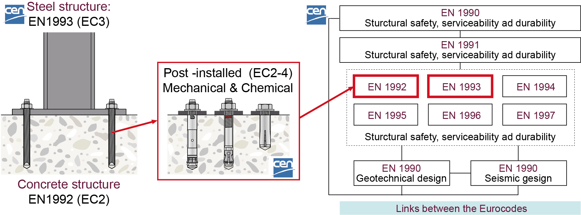
With EN 1992-4 for concrete fastenings, the regulatory
framework for steel-to-concrete connection design has been further extended.
Concrete fastenings have been included under concrete structural design in Eurocode 2 as they are a safety-relevant application linking steel structures to reinforced concrete. If you haven’t paid much attention to concrete fastening design in the past, or have left anchor design decisions to a contractor, now may be the time to take fastening design more seriously.
If you’ve previously been designing concrete fasteners according to ETAG 001 (guideline for European technical approval for metal anchors), it’s important to note that while the overall design concept remains the same, EN 1992-4 introduces some important technical changes with regard to calculating the resistance of fastenings.
Fastener performance, meanwhile, must continue to be taken from the European Technical Assessment (ETA) document of the anchoring system in the case of anchor design.
Let’s go through some of the changes you will experience when switching from the ETAG 001 guideline to the EN 1992-4 standard.
Change 1: Clear scope of design
EN 1992-4 explicitly points out that the code covers both structural and non-structural applications if there is a safety concern.
It also covers the entire scope of anchor design compared with ETAG 001 in terms of concrete strength coverage (from C12/15 up to C90/105) and provides more anchor layout configuration options.
Change 2: Shift in concrete strength evaluation from cubic to cylindrical samples
The original equations for determining concrete-related failure loads, such as concrete cone failure and concrete edge failure, were determined by considering the concrete compressive strength of concrete cubes with an edge length of 200 mm. When transferring the design concept to other fastening systems or guidelines, the corresponding equations were given with reference to a concrete compressive strength of concrete cubes with an edge length of 150 mm.
As part of the revisions made to the European standard, the equations in question were adjusted to reflect the cylindrical compressive strength (150 mm x 300 mm). Based on this adjustment, up to 4–5% lower resistance values are calculated in EN 1992-4.
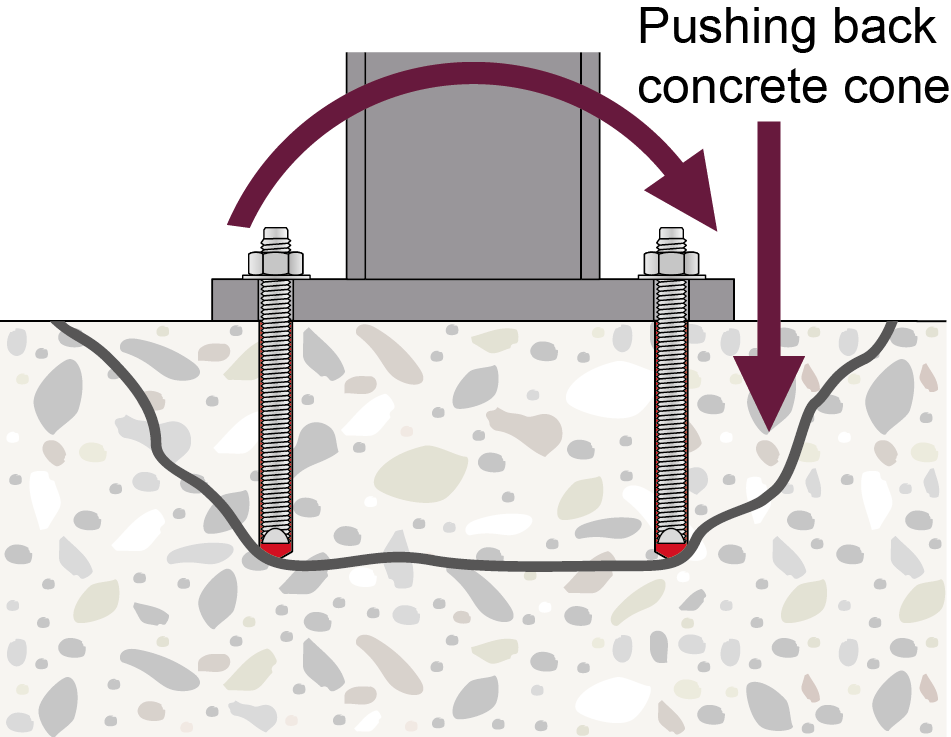
Change 3: Possibility of increased concrete cone failure resistance during a bending moment
When concrete anchor fastenings are subjected to a moment of force, one side of the base plate should be working under tension whereas the other will be working under compression. EN 1992-4 considers the positive effect of the compression force acting on the concrete surface, which may increase concrete cone resistance in specific conditions. ETAG 001 does not take this effect into consideration.
EN 1992-4 considers the positive effect of
the compression force acting on the concrete
Change 4: Creep behavior of chemical anchors under permanent (sustained) loads
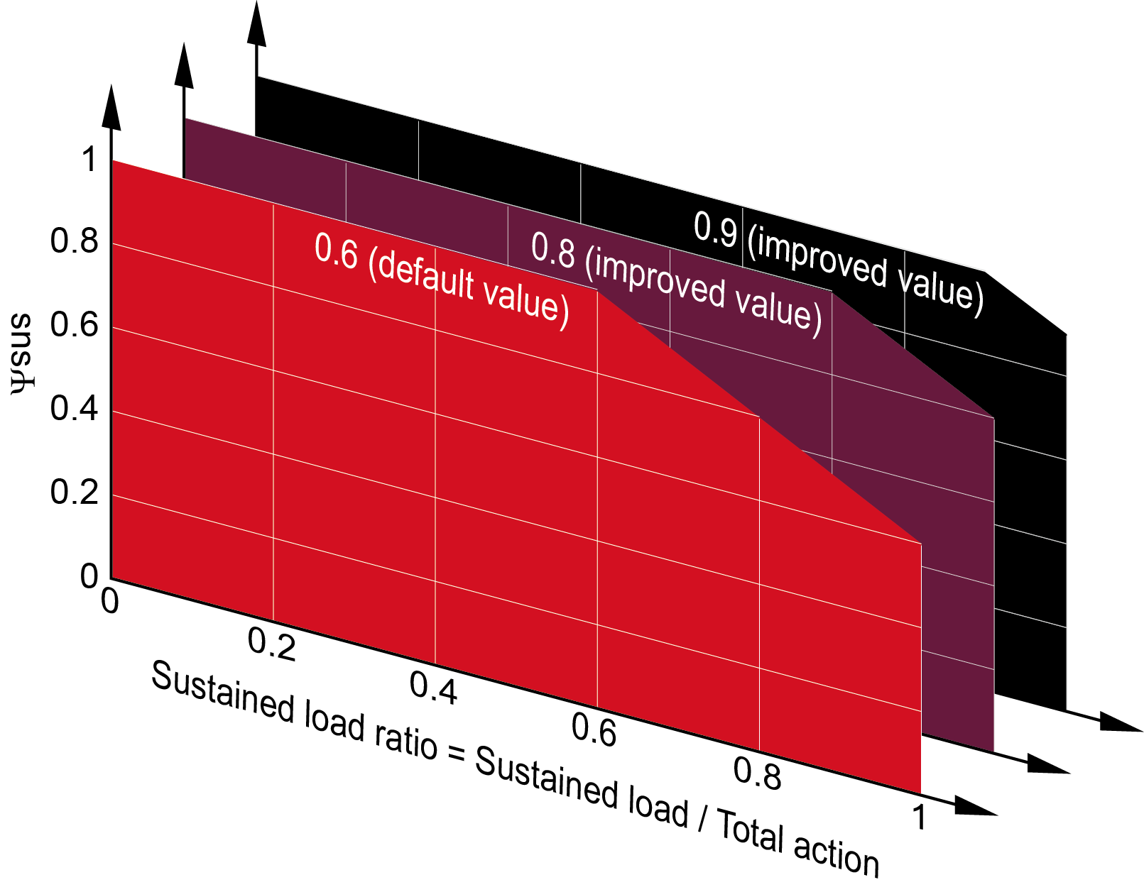
A new sustained load factor for chemical mortars ψsus is introduced in EN 1992-4 to take account of their potential creep behavior.
This factor depends primarily on the ratio of sustained loads to total actions: conceptually, after a certain ratio, the higher the percentage of sustained load (e.g. dead load) against total load, the higher the strength reduction.
Secondly, the product performance ψ0sus stated in the ETA document is taken into account. If no additional information regarding this factor is provided in the ETA, it is considered to be 0.6.
For example, let’s take a product whose ψ0sus is 0.8 according to its ETA. This means that if the sustained load ratio is below 80%, the resistance will not be reduced due to creep, but if the sustained load is 90%, the resistance of this failure mode will be reduced by 10% (ψsus = 0.9). The chart below illustrates different potential scenarios.
A sustained factor may be considered
in the design of chemical anchor solutions in EN 1992-4.
Change 5: More flexibility to neglect splitting failure
Although the calculation method remains unchanged, there are more cases in which this failure mode can be omitted from the calculation. To neglect the verification of this failure mode, the required member thickness is reduced from 2 hef (as per ETAG 001) to hmin (as per EN 1992-4).
Change 6: Adjustment to concrete edge failure formula
There are several detailed equation changes in EN 1992-4 compared with ETAG concerning the failure mode resistance calculation, such as the effective length for edge failure, the existing rebar influencing factor and the action direction influencing factor. All of these changes can lead to the possibility of reduced resistance, but the circumstances in which these changes can occur are rare.
Another aspect for designers to note is that the calculation method does not cover the lever arm effect on the concrete edge. This means they must consider additional safety factors when calculating edge failure under this condition.

Lever arm effect on the concrete edge is not covered by EN 1992-4
Change 7: Steel failure of stand-off installations with grouting under shear loads
Steel resistance is reduced to a great extent when there is a shear action lever arm, as per the previous ETAG design. However, the ETAG consideration was extremely conservative even in uncracked concrete design. EN 1992-4 provides an alternative solution that considers the positive effect of grouting on the stand-off base plate.
However, this alternative method only applies when:
1) there are at least two anchors in a group;
2) there is no tension acting on the base plate;
3) the concrete is considered to be uncracked;
4) the grout thickness does not exceed 40 mm or more than five times the diameter of the anchor;
5) the grout compression strength is more than 30 MPa;
6) there is a roughened concrete surface beneath the stand-off base plate.

EN 1992-4 considers the effect of grouting
on shear load transferal in stand-off applications under certain conditions.
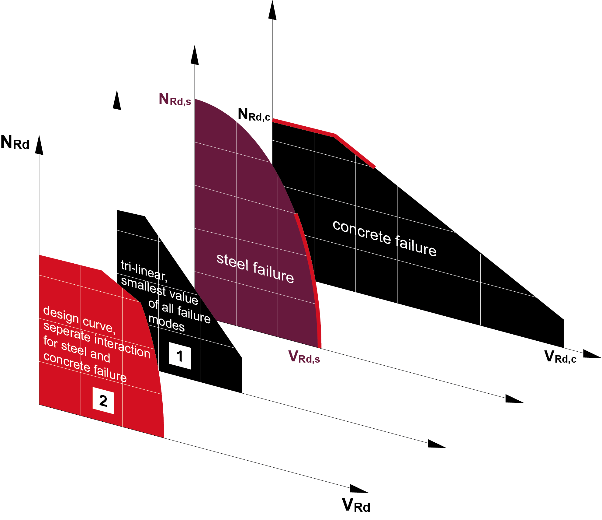
Change 8: Separate consideration of steel and concrete for combined tension and shear failure
When the resistance of combined tension and shear failure is calculated according to ETAG 001, only the worst utilization under tension and shear loads is taken into account, without considering that one may be steel failure and the other concrete. This approach is very conservative as ETAG combines two different failure types.
EN 1992-4 specifies that steel failure and concrete-relevant failure modes should be considered separately, thereby potentially delivering higher utilization values than ETAG, especially under seismic conditions.
Unlike ETAG 001, EN 1992-4 treats steel failure and concrete-relevant
failure modes separately.
These changes may seem daunting to begin with, so please feel free to reach out to us. Our approvals have been updated according to the new European Assessment Documents (EADs), and our PROFIS Engineering software is fully compliant with the new design standard. Don’t limit yourself to anchor design, either: PROFIS Engineering Premium is the perfect tool to design the full connection according to Eurocodes, including the base plate, stiffeners, welding and profile, and to assess the effective rigidity of the base plate as required by anchor design provisions. Efficient and all in one place.

The EN 1992-4 based anchor calculation method is integrated into PROFIS Engineering.
